Hard disk drives (HDDs) have long been critical to personal computing and cloud platforms. Thees devices store trillions of files, from photos and videos of our daily lives to professional projects. Without hard drives, the world would struggle to store vast amounts of digital data.
Yet, how a hard drive works remains a mystery to many people.
Hard drives store data using write heads to magnetize domains on spinning platters. Read heads retrieve data from disks by detecting a domain’s magnetic field. Each region on the magnetic platter has a value that represents a 0 or 1 based on its polarity. These binary bits form the foundation of digital data.
The experts at Secure Data Recovery, a global leader in data recovery services, explain what makes hard drives spin.
What Is a Hard Drive?
A hard drive is an electromechanical device that stores user data and system files for a computer or server.
Unlike a solid-state drive (SSD), HDDs use a series of mechanical components to save data. These moving parts include spinning platters coated with magnetic material and microscopic read/write heads to retrieve or record data. Each component plays a key role in how hard drives work.
Fun Fact: IBM developed the first hard disk drive in 1956. The IBM 350 Disk Storage Unit housed 50 magnetic platters, all measuring 24 inches in diameter. Its cabinet occupied as much space as two refrigerators and weighed just under a ton. The device stored less than 5 megabytes of data and sold for $35,000. That sum is equivalent to over $400,000 in 2025.
Components Inside a Hard Disk Drive
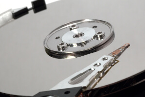
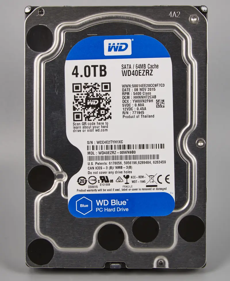
For this exercise, our engineers removed the hard drive from its case to showcase internal components.
The test subject was a 4 TB WD Blue desktop hard drive. It has a 3.5-inch form factor and SATA connectors. We chose the WD40EZRZ because it is a popular model with a conventional design.
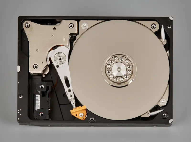
The above image reveals what someone would see if they lifted the lid on their device.
However, this overhead view still conceals the inner workings of a hard drive.
Here are the main components found inside a hard disk drive:
Platters
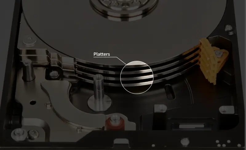
Platters are rigid disks that store data by magnetizing tiny regions on their surface.
Made of a durable substrate (such as aluminum or glass), platters can withstand high-speed rotation. During production, disks receive a thin layer of magnetic material and a protective carbon overcoat. The film allows the device to both retrieve (read) and record (write) data on the platter surface by sensing or altering its magnetization.
The service area is an inaccessible region of the platter that keeps most of the device’s firmware. Firmware is embedded, low-level software that enables the drive to function properly. The service area includes mapping, defect lists, parameter tables, and diagnostic logs.
Some hard drives stack multiple platters on a spindle to increase their storage capacity.
Fun Fact: Most hard drives write data to both sides of a platter to maximize their limited surface area.
Spindle Motor
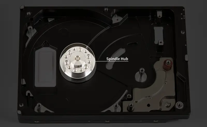
The spindle motor sits at the center of the drive’s base and spins the platters at a constant speed.
The motor consists of two separate assemblies. The stator is a stationary array of electromagnets wound around iron cores. The rotor is a ring of permanent magnets bonded to the inner wall of the spindle hub.
Direct current (DC), switched through the stator coils, creates a rotating magnetic field. That field produces torque on the permanent magnet rotor in the central hub. The subsequent force causes the hub to rotate on a fluid dynamic bearing around a fixed shaft.
As a result, the disks spin at the rated speed.
Fun Fact: The spindle motor in most consumer HDDs turns the platters at 5400 or 7200 revolutions per minute (RPM). That means typical platters spin 90 or 120 times per second.
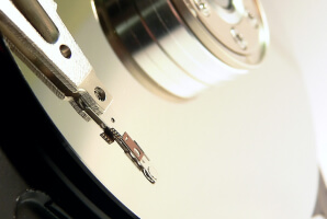
Actuator Arm
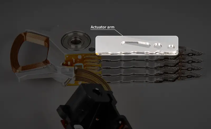
The actuator arm is a lever that positions critical components over different regions of the platter surface.
Like the tonearm of a record player, the actuator arm is joined to a pivot point for smooth movement. Its structure is rigid enough to minimize vibration and withstand turbulence while in use. The arm also houses a cable that carries both electric current and signals crucial to storing data.
Fun Fact: Seek time measures how long it takes the actuator arm to move from its current track to another position on the platter. Short seeks can happen in about 1 millisecond. A human blink lasts between 100 and 400 milliseconds on average.
Voice Coil Motor
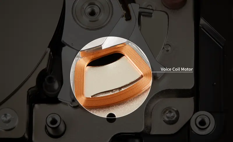
The voice coil motor (VCM) powers the actuator arm by passing a current through a coil of copper wire within a magnetic field.
The primary element of the motor is a voice coil located at the base of the actuator arm. A pair of neodymium magnets sits above and below the coil of conductive wire. These objects are the strongest permanent magnets currently available.
The wire becomes an electromagnet when it receives a controlled current. The permanent magnets nearby generate a force that causes the actuator arm to sweep across the disk. A reverse current sends the arm in the opposite direction. This process provides precise control over the actuator arm’s position on the platter.
Fun Fact: The command current in the voice coil is constantly adjusted to counter other forces. Often, the current ramps and reverses tens of thousands of times per second. These continuous adjustments enable the drive to land within nanometers of its target.
Read/Write Heads
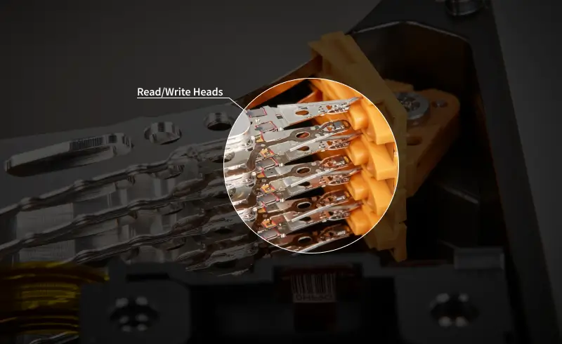
Read/write heads are the tiny instruments that record and retrieve data on magnetic platters.
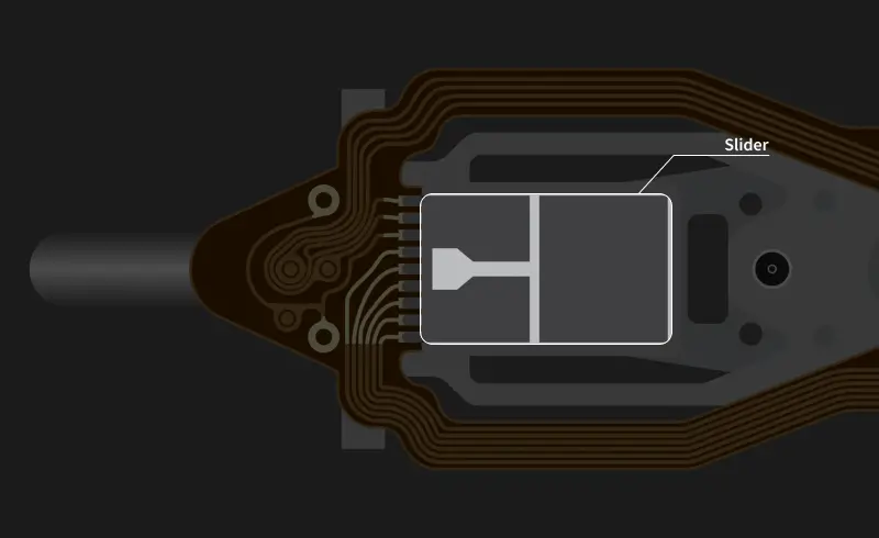
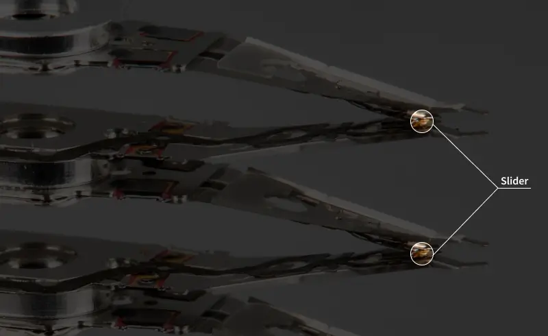
Heads are mounted to a slider. This aerodynamic piece flies atop a thin air cushion formed by the spinning disk. In modern hard drives, the slider floats about 3 to 5 nanometers (nm) above the platter surface. By comparison, a sheet of paper is about 100,000 nm thick.
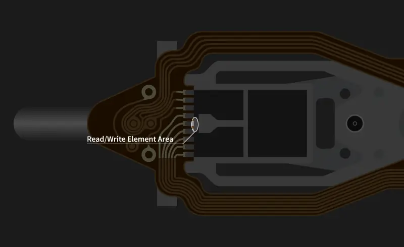
Read/write heads have two main elements. A read element is a magnetic sensor that detects reversals in polarity on the platter. The transition between regions signifies a change from 0 to 1 or 1 to 0 in binary data. A write element is an inductive coil that uses an electric current to create a localized magnetic field. The small field flips the magnetization of a region. Flipping magnetized regions encodes data by establishing patterns of opposite orientations on the platter.
Fun Fact: Read/write heads are around 1 millimeter (mm) long. For context, a grain of rice is between 5 and 10 mm long.
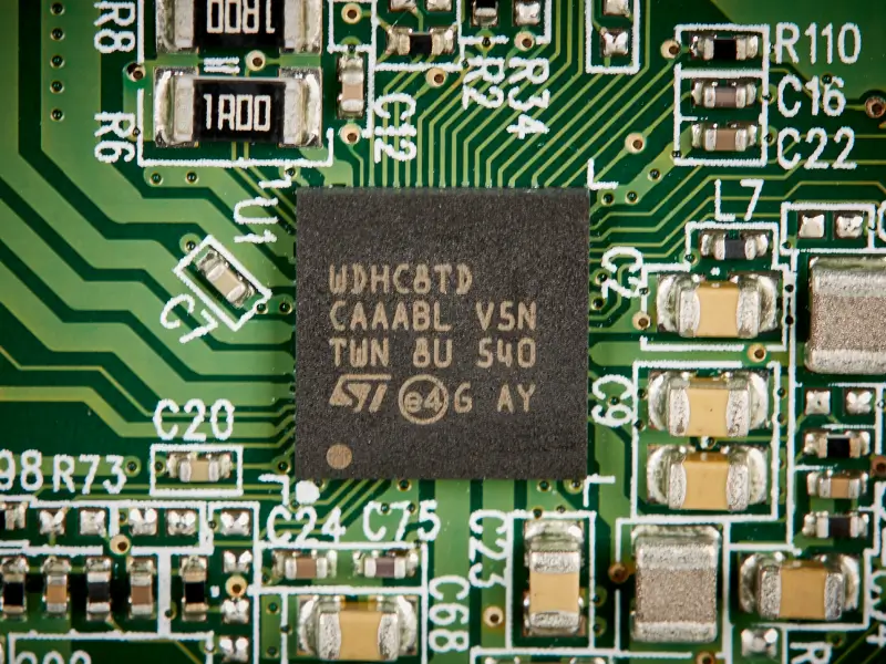
Preamplifier
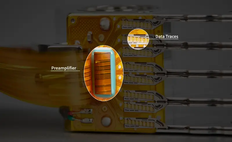
The preamplifier is an integrated circuit that boosts read signals and drives write current for selected heads.
The preamp is located on a flexible film closer to the read/write heads to reduce signal loss. It is the first chip to receive data after a read operation is complete. Conversely, it is the last chip to transmit instructions before a write operation. Preamps have evolved to provide cleaner, higher gain, and wider bandwidth. These advancements help amplify very weak signals with maximum clarity.
Fun Fact: The preamp is typically the only chip inside the sealed compartment of a hard disk drive.
Printed Circuit Board (PCB)
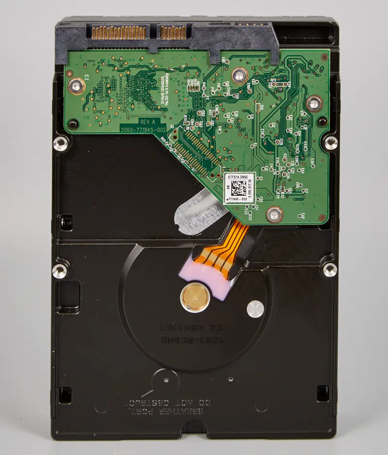
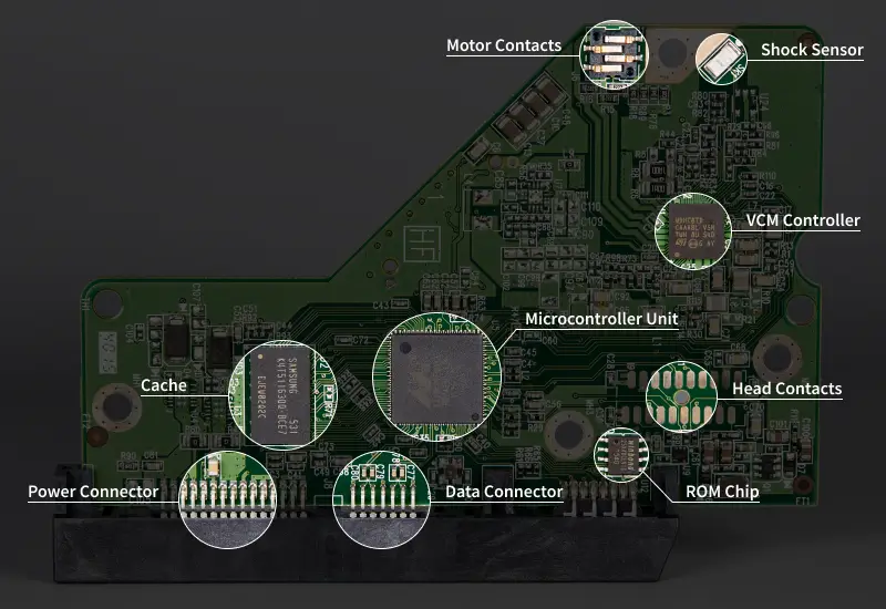
The printed circuit board (PCB) features a collection of integrated circuits and electronics that manage data transfers and regulate power throughout the drive.
The PCB is a flat piece of layered fiberglass with copper traces linking processors, memory, and support chips. The board is mounted to the exterior of the device.
In simple terms, the PCB is like the HDD’s control center.
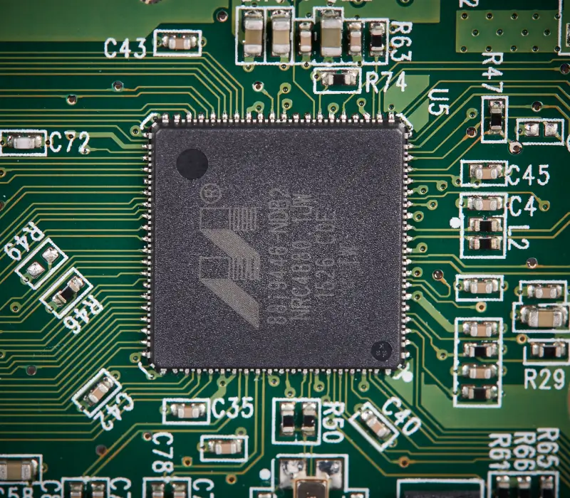
Often located in the middle of the PCB, the microcontroller unit (MCU) is the central processor of a hard drive. It includes a control unit, registers, an arithmetic logic unit (ALU), and an instruction pipeline.
The control unit interprets instructions from the drive’s firmware and then issues commands. Registers are ultra-fast memory cells to store active inputs and values. The ALU calculates operations as needed. The instruction pipeline sorts the next steps for each component of the MCU.
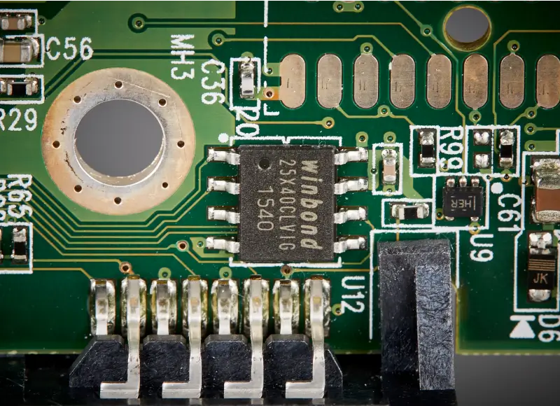
A tiny, read-only memory (ROM) chip near the controller holds board-specific firmware.
As mentioned, firmware is low-level software for the device. This code identifies the disk to the host computer. It also runs boot tasks, such as spinning platters and positioning the actuator arm. Firmware is stored in flash memory so its code persists without power.
Some hard drives store firmware inside the MCU instead of soldering a separate ROM chip to the PCB.
Fun Fact: The ROM chip contains part of the drive’s adaptive data alongside the service area. Adaptive data is a unique set of values calibrated to that exact HDD. The presence of adaptives makes PCB swaps more complex because all values must match for the disk to function.
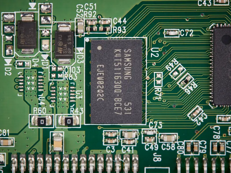
The cache is a small pool of random-access memory (RAM) that stores working data.
The cache acts as a buffer between the PCB and magnetic platters. It maintains recently read data and pending writes to improve performance. Cache size ranges from 64 MB to 512 MB, depending on the model.
The voice coil motor controller is a combined circuit that feeds electric current to move the actuator arm and energize the spindle.
The VCM controller receives constant feedback from a servo system that measures head position and orders adjustments. It also controls the amount of torque provided by the spindle motor to maintain the target RPM. Closed-loop tracking algorithms alter the current to each motor while the drive is still running.
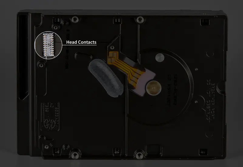
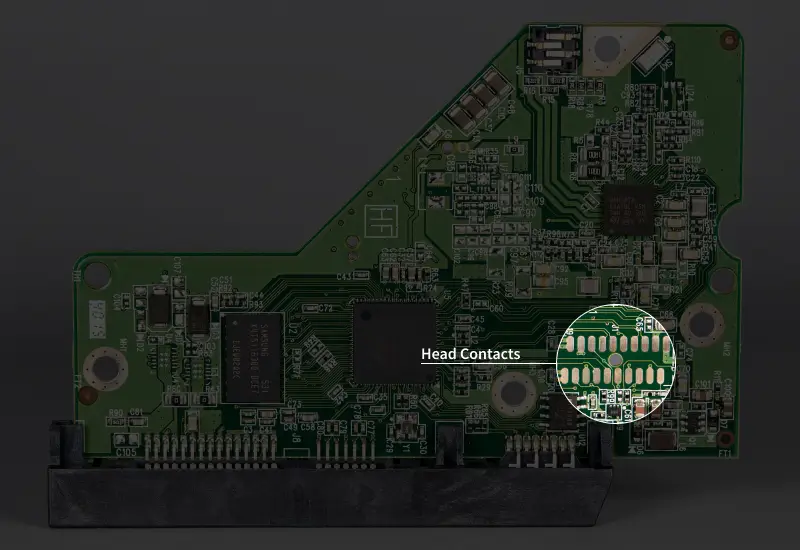
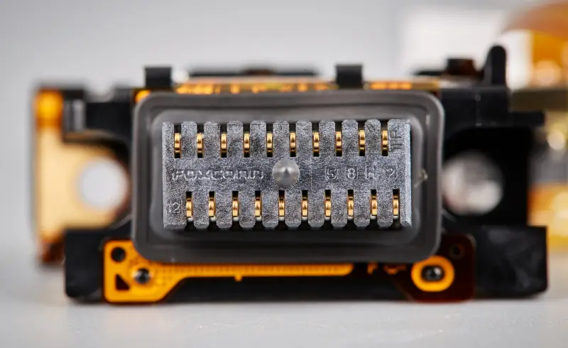
Head contacts establish a direct, reliable connection between the PCB and the read/write heads through the flex cable. The cable mates to a terminal on the PCB and bonds to pads on the preamp.
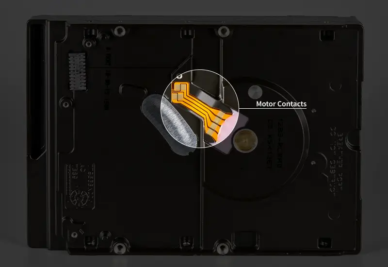
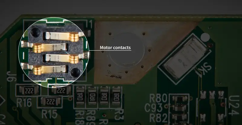
Likewise, motor contacts link the PCB to the spindle motor for controlled rotation.
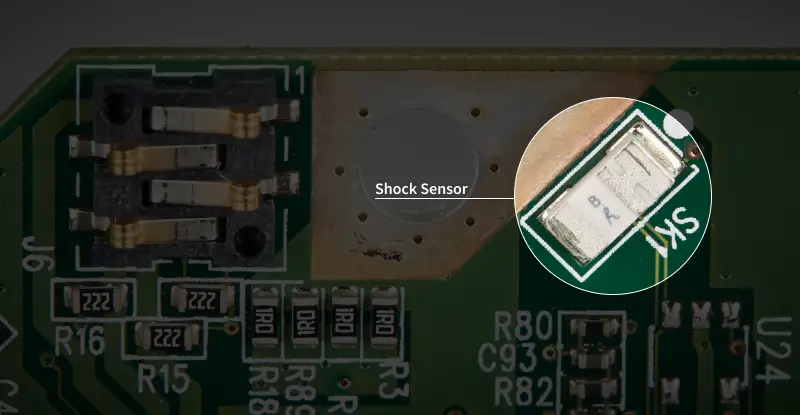
Shock sensors detect sudden impacts or vibrations and mechanical stress. If an event surpasses a threshold, the device parks the read/write heads in a ramp to protect the platters.
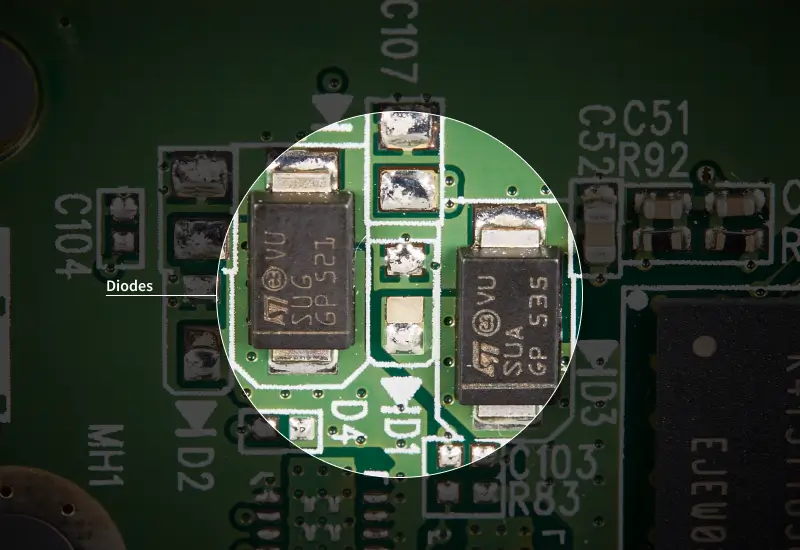
Diodes allow current to flow in one direction. Transient voltage suppression (TVS) diodes on the PCB divert surge current during a power spike and prevent damaged circuits.
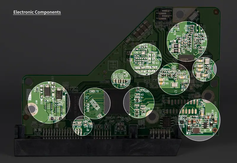
Other electronic components serve essential roles on the PCB. Transistors are semiconductors that manage electric currents and signals across the PCB. Resistors are a passive component that restricts current within a circuit. Capacitors are a passive component that store electric charges to support power demands.
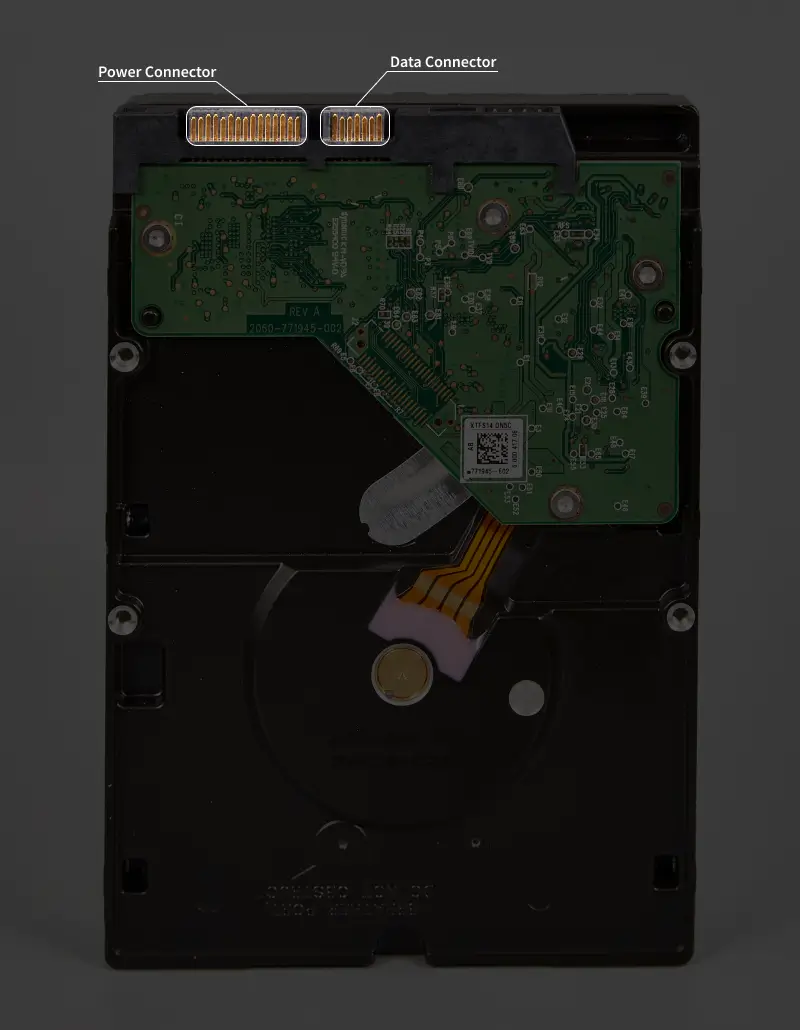
The power connector is a pinout that delivers power to the storage device. The data connector is a pinout that creates a point-to-point link with the motherboard. This connection exchanges commands and data between the drive and host system. Most hard drives carry that traffic over a SATA interface.
Overall, the chips and other components on the PCB enable data storage.
Fun Fact: A hard drive’s PCB handles millions of tasks per second to seamlessly manage data.
How a Hard Drive Organizes Data
The platter surface contains billions of magnetic domains. Bits of digital data (0 or 1) are encoded across many domains by alternating patterns of magnetic orientation (up and down).
Continuous streams of bits fill concentric paths on the platter, known as tracks. Each track is divided into blocks called sectors. Sectors hold a fixed amount of user data and error-correcting code (ECC). ECC detects and corrects minor errors in the sector’s data. A logical block address (LBA) identifies every sector. LBA is a linear numbering scheme that corresponds to a physical location on the platters.
An operating system (OS) interacts with a disk’s geometry through a file system. It groups consecutive sectors into a cluster. When a system creates, edits, or opens a file, it works with clusters instead of a single sector.
The layered structure transforms magnetic disks into usable storage space.
Fun Fact: Most modern hard drives store 4 kilobytes of user data per sector. In other words, platters pack almost one billion sectors across their entire surface to store 4 terabytes of data.
How a Hard Drive Works: The Science Behind HDDs
Reading and writing data on a hard drive occurs in four stages:
- Control: The MCU and firmware orchestrate all tasks, from commanding current to the motors to scheduling read and write operations.
- Mechanical: The spindle motor rotates the platters, providing a stable environment for recording and retrieving data.
- Positioning: The actuator arm moves to a target track on the platters and remains at that location.
- Signal: The read/write heads convert magnetization to electric signals, which other components decode or encode into digital data.
The pipeline is a closed loop. The drive’s controller and firmware begin the sequence and make continuous adjustments based on feedback received during each stage. Once the current task is complete, the controller will advance to the next request. This process repeats until the device is powered down.
Here is a step-by-step breakdown.
How Hard Drives Read Data
Control:
- The OS requests to open a file.
- The MCU queues the command and checks the cache for that data.
- If the file is not cached, the firmware translates the address to a physical location on the platter.
- The MCU selects the proper zone and track and commands the VCM controller to produce the necessary current.
Mechanical:
- The spindle motor holds a constant RPM, allowing the platters to pass at the expected rate.
Positioning:
- The actuator arm receives a controlled current that propels it toward the target track.
- The servo system measures position while sweeping across the platter.
- The actuator arm draws a reduced current as it nears the physical location.
- The current to the actuator arm ramps or reverses to keep the head centered on the right track and sector.
Signal:
- The head’s read sensor picks up transitions in magnetized regions.
- The preamp boosts the electric signals and routes them to the PCB.
- A channel on the MCU cleans the signals, corrects minor errors, and detects the digital data.
- The channel sends digital data to the cache for quick access.
- The MCU sends data to the OS across the interface (SATA, SAS, etc).
- Queued reads may merge if they are adjacent to the current one.
When the hard drive finishes reading that data, it proceeds to the next task or idles.
How Hard Drives Write Data
Control:
- The OS submits a request to save a file.
- The MCU queues the command and follows its write cache policy. Most drives save data in the cache for quick access and then commit it to the media later.
- The firmware maps data to a physical location on the platter.
- The MCU chooses the target zone and track on the disk and instructs the VCM controller to direct current to the motors.
Mechanical:
- The spindle motor sustains its rated RPM for spinning platters.
Positioning:
- The actuator arm moves toward the selected track because of a controlled current in the voice coil motor.
- The servo system constantly monitors the arm’s position over the platters.
- The actuator arm receives a tapered current as it approaches the desired location.
- The voice coil motor slightly alters the supplied current to maintain position above the right track and sector.
Signal:
- The MCU turns digital data into a stream of bits and transmits them to the preamp.
- The preamp sends a current to the head’s write element to flip the orientation of magnetized regions.
- Queued writes may be performed together for sequential data.
After writing data to the disk, the drive typically flushes the cache and continues to the next step.
Magnetic Recording Technologies
Manufacturers have developed new magnetic recording methods since the invention of hard drives. Upgraded recording methods are one of the most straightforward paths to making larger disks.
Most hard drives use conventional magnetic recording (CMR). CMR deposits bits in layers along concentric tracks on the platter. It improved upon the density of legacy drives by condensing domains on the disk and using a more coercive magnetic material.
Shingled magnetic recording (SMR) is a standard method in consumer HDDs with higher storage capacities. SMR drives feature platters with overlapping tracks. The arrangement of tracks on the platter is similar to shingles on a roof. However, SMR has performance trade-offs compared to CMR.
Heat-assisted magnetic recording (HAMR) and microwave-assisted magnetic recording (MAMR) are next-gen tech in enterprise hard drives. These methods use energy to heat platters briefly and write data at ultra-high density. They have been deployed in data centers to meet surging demand.
Although hard drives share the same parts, recording methods are a key difference that affects how disks behave and perform.
Fun Fact: Modern hard drives have a cost per gigabyte around $0.02. It would have cost over $9 million to store a gigabyte of data using IBM’s first disk. That figure exceeds $100 million in 2025 dollars.
Hard Drive Enclosure
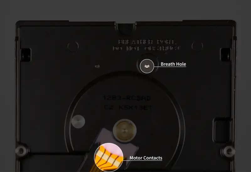
A hard drive’s enclosure is also a vital part of the device. The case is often made of an aluminum alloy to help dissipate heat. The cover includes rubber gaskets and steel screws to prevent dust, debris, and other harmful substances from reaching delicate components. Most HDDs have a breath hole to equalize internal and external air pressure for a stable atmosphere.
Fun Fact: Some hard drives are filled with helium and then sealed shut. Why helium? It is about seven times less dense than regular air. As a result, helium drives have much less drag and cooler temperatures. The steady state means these disks can hold more platters and lower the total cost of ownership.
Common Causes of Hard Drive Failure
Hard drives fail for three reasons:
- Physical Damage: Bad sectors, scratched or warped platters, bricked controllers, blown electronics, and bent components.
- Mechanical Failure: Torn, stuck, or weak read/write heads, seized motors, and worn bearings.
- Logical Errors: File corruption, missing partitions, malware infection, and flawed firmware.
Hard drive clicking or beeping, sluggish performance, repeated file errors, and fatal system crashes are symptoms of HDD failure. Recognizing these warning signs and acting quickly can preserve important data.
Following the 3-2-1 Backup Rule is the best strategy to prevent data loss.
Yet, sudden data loss still happens despite backup efforts.
Secure Data Recovery has provided professional hard drive recovery since 2007. Our certified engineers have decades of experience and expertise across all hard drive failures. Call 800-388-1266, request help, or find a location to start a case and receive a free quote, along with our No Data, No Recovery Fee guarantee.
Frequently Asked Questions
What is inside a hard disk drive (HDD)?
The main components of hard drives include:
- Magnetic platters to store data.
- A spindle motor to rotate platters.
- A voice coil motor to move the actuator arm.
- Read/write heads to record and retrieve data on platters.
- A preamplifier to boost signals and drive current to read/write heads.
- A printed circuit board (PCB) with specialized chips and other electronics to manage all operations.
These components are the foundation of a hard disk drive.
How does a hard drive work in simple terms?
A hard drive spins magnetic platters at a constant RPM. A pivoting actuator arm positions read/write heads above the platter surface. The heads detect magnetized regions on the platter to read data. They alter the platter’s magnetization to write new data. A complex printed circuit board (PCB) oversees the entire process.
Where does the hard drive receive data from?
Read and write requests come from the computer. The system relays the requests over an interface that links the motherboard and hard drive. Once the command arrives, the HDD loads stored data and transfers it to the host or saves it to the disk.
What is the difference between a hard drive and SSD?
Hard drives store data on magnetic platters using moving parts. SSDs store data by trapping electric charges in flash memory cells. The design difference leads to storage devices that fare better in specific roles. Hard drives excel at storing large volumes of data at a lower price. SSDs offer more performance than spinning disks. Higher speeds are ideal for multitasking, heavy workflows, and gaming.
How long do hard drives last?
It depends. We studied hard drive lifespan and found that disks sent to our lab failed after 25,233 power-on hours. That equates to 1,051 days (or 2 years and 10 months). Some hard drive maintenance tips can prolong their life, but failure is inevitable. That is why backing up data is essential.

Timothy Burlee

Timothy Burlee is a content writer for Secure Data Recovery Services. He specializes in various topics in the data industry, including data recovery technology, storage devices, and digital forensics. Throughout his career, he has covered complex concepts and provided accessible solutions for users. Before joining Secure Data, he worked as a freelance technical writer.